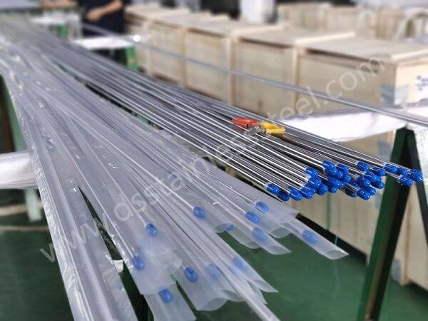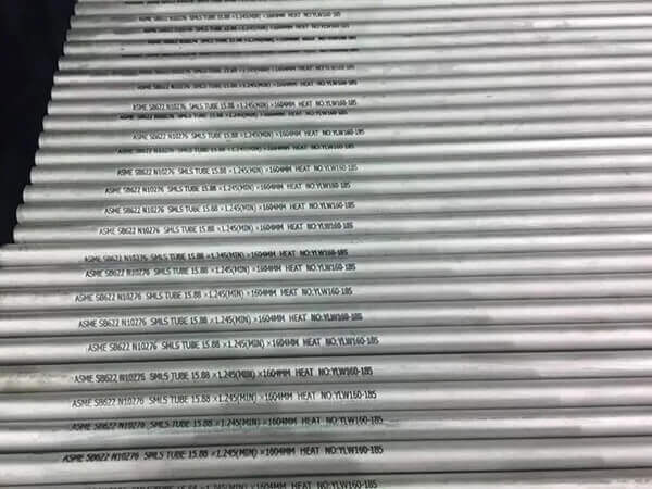
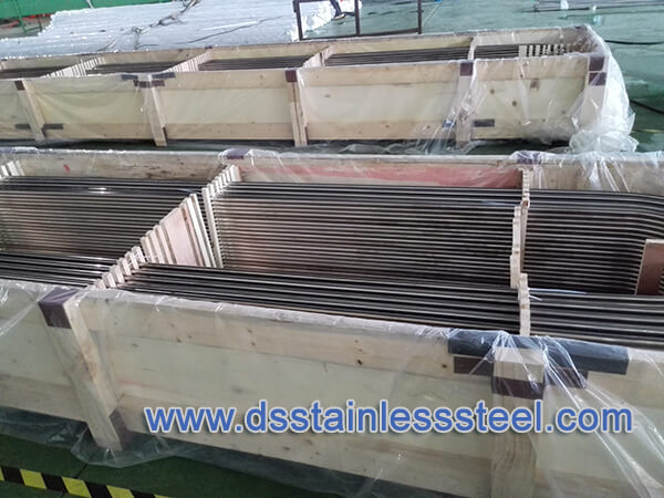
We offer ASTM B163 UNS N04400 seamless tube for use in the condenser and heat-exchanger service, SB163 400 seamless tube specifies sizes on the outside diameter and average wall, or outside diameter and minimum wall tube. UNS N04400 Nickel alloy seamless tubes exhibit excellent ductility and toughness and have outstanding resistance to corrosion and high temperatures.
The sizes covered by ASTM B163 specification are 3 in. (76.2 mm) and under in outside diameter with minimum wall thicknesses of 0.148 in. (3.76 mm) and under, and with average wall thicknesses of 0.165 in. (4.19 mm) and under. small diameter and light wall tube (converter sizes) are defined.
ASTM B163 UNS N04400 Tube Specifications
| Standard | ASTM B163, ASME SB163 |
|---|---|
| Tube Type | Seamless Tube |
| Alloy | UNS N04400 400 |
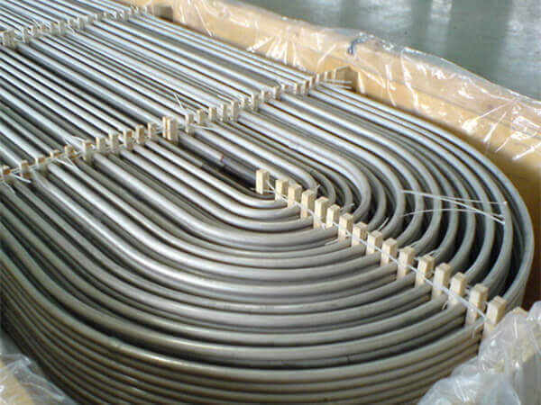
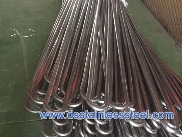
| tube form | Straight tubes and U-bend tubes |
| Outside Diameter | 6 – 76.2 mm |
| Thickness | 0.8 – 6 mm |
ASTM B163 UNS N04400 Chemical Composition
ASTM B163 UNS N04400 is a nickel-copper alloy containing more than 63.0% nickel and 28.0-34.0% copper content, it can be hardened only by cold working. It has high strength and toughness over a wide temperature range and excellent resistance to many corrosive environments. EN equivalent is WNR 2.4360.
| Alloy | Nickel | Copper | Manganese | Iron | Sulfur | Carbon | Silicon | Chromium |
|---|---|---|---|---|---|---|---|---|
| UNS N04400 | 63.0 min | 28.0 – 34.0 | 2.0 max | 2.5max | 0.024 max | 0.3max | 0.5 | … |
ASTM B163 UNS N04400 Mechanical Properties
| Material and Condition | Tensile Strength Min. Ksi(MPa) | Yield Strength(0.2% Offset)Min,Ksi(MPa) | Elongation in 2in. or 50mm(or 4D)min. % | Rockwell Hardness(or Equivalent) for Annealed Ends[Note(1)] |
|---|---|---|---|---|
| Stress-relieved Alloy UNS N04400: | 85(586) | 55(379) | 15 | B75max |
Tolerances In Outside Diameter And Wall Thickness
| Material | Nominal Outside Diameter, In. (Mm) | Permissible Variations [Note(1)] | |||||
|---|---|---|---|---|---|---|---|
| Outside Diameter, In. (Mm) | Wall Thickness, % | ||||||
| Anerage Wall | Minimum Wall | ||||||
| + | – | + | – | + | – | ||
| UNS N02200, UNS N02201, And UNS N04400 | Average Wall | 0.005(0.13) | 0 | 12.5 | 12.5 | 25.0 | 0 |
| 8/5 To 1 1/2(15.9 To 38.1), Incl | 0.005(0.13) | 0.005(0.13) | 10.0 | 10.0 | 20.0 | 0 | |
| Over 1 1/2 To 3(38.1 To 76.2), Incl | 0.010(0.25) | 0.010(0.25) | 10.0 | 10.0 | 22.0 | 0 | |
| UNS N06600, UNS N066090, UNS N06045, UNS N06025, UNS N08800, UNS N08810, UNS N08811, UNS N08801, And UNS N08825 | 1/2 To 5/8 (12.7 To 15.9), Excl | 0.005(0.13) | 0.005(0.13) | 12.5 | 12.5 | 25.0 | 0 |
| 8/5 To 1 1/2 (15.9 To 38.1), Incl | 0.0075(0.19) | 0.0075(0.19) | 10.0 | 10.0 | 20.0 | 0 | |
| Over 1 1/2 To 3 (38.1 To 76.2), Incl | 0.010(0.25) | 0.010(0.25) | 10.0 | 10.0 | 22.0 | 0 | |
U-Bent Tubes
The requirements for U-bent tubes included in this supplement are limited to the alloys, conditions (tempers), tube outside diameter (OD), and wall thickness ranges and bend radii listed in the Table below.
Permissible Variations in Dimensions.
Leg Spacing – The leg spacing, measured between the points of tangency of the bend to the legs shall not vary from the value (2R – specified tube OD) by more than the amounts shown below where R is the specified centerline bend radius:
| Centerline Bend Radius (R), in. (mm) | Tolerance, in.(mm) |
|---|---|
| Up to 18 (457), incl | 1/16(1.6) |
| Over18 to 30 (457 to 762), incl | 3/32(2.4) |
| Over 30 to 36(762 to 914), incl | 1/8(3.2) |
Diameter of Tube in U-Bent Section – Neither the major nor the minor outside diameter of the tube at any cross section included within the points of tangency of the bend shall deviate from the nominal diameter before bending by more than 10%.
Wall Thickness of Tube in U-Bent Section -The wall thickness of the apex of the U-bent section shall be not less than the value determined by the following equation: Tf=T(2R)/(2R + D) where
Tf = thickness after bending, in.(mm)
T = minimum permissible thickness of tube wall before bending, in. (mm)
R = centerline bend radius, in. (mm),
and D = nominal outside diameter of the tube, in. (mm).
When specified by the purchaser, proof of conformance to this requirement shall be obtained by bending a tube specimen, representative of the material offered, to the scheduled radius of bend, cutting the tube at the apex of the bend, measuring the tube wall at the cross-section of this apex section, and comparing the measured value with the calculated value of Tf
Length of U-Bend Tube Legs – The length of the tube legs as measured from the point of tangency of the bend and the tube leg to the end of the tube leg shall not be less than that specified but may exceed the specified values by the following amounts:
ALLOY [NOTE (1)], CONDITION, TUBE SIZE, AND BEND RADII LIMITATIONS
| Tube 0D, in. (mm) | Average Tube Wall, in. (mm) [Note (2)] | Minimum Bend Radius, in. (mm) | |
|---|---|---|---|
| Annealed Condition | Stress-Relieved Condition | ||
| Up to 1/2 (12.7), incl | 0.046to 0.057(1.17 to 1.45), incl | 1 3/16(30.2) | 1 1/4 (31.8) |
| Up to 1/2 (12.7), incl | Over 0.057 to 0.120 (1.45 to 3.05), incl | 1(25.4) | 1 1/8 (28.6) |
| Over 1/2 to 5/8 (12.7 to 15.9) incl | 0.037 to 0.057 (0.94 to 1.45), incl | 1 3/16 (30.2) | 1 1/4 (31.8) |
| Over 1/2 to 5/8 (12.7 to 15.9) incl | Over 0.057 to 0.120 (1.45 to 3.05), incl | 1 (25.4) | 1 3/16 (30.2) |
| Over 5/8 to 3/4 (15.9 to 19.0) incl | 0.049 to 0.057 (1.24 to 1.45), incl | 1 1/4 (31.8) | 1 1/2 (38.1) |
| Over 5/8 to 3/4 (15.9 to 19.0) incl | Over 0.057 to 0.109 (1.45 to 2.77), incl | 1 3/16 (30.2) | 1 1/4 (31.8) |
| Over 3/4 to 1 ( 19.0 to 25.4) incl | 0.049 to 0.058 (1.24 to 1.47), incl | 2 (50.8) | 4 (101.6) |
| Over 3/4 to 1 (19.0 to 25.4) incl | Over 0.058 to 0.109 (1.47 to 2.77), incl | 1 3/4 (44.5) | 2 1/4 (57.2) |
NOTES:(1) Applies for all alloys except Allpy UNS N08810, Alloy UNS N08801. and UNS N08811.
(2) To determine the bend radius applicable to minimum wall tubing, compute the corresponding average wall from the wall tolerances in Table 5, then use Table 6.
ASTM B163
Standard Specification for Seamless Nickel and Nickel Alloy Condenser and Heat-Exchanger Tubes
ASTM B163 specification covers seamless tubes of nickel and nickel alloy for use in condenser and heat exchanger service. This covers outside diameter and average wall, or outside diameter and minimum wall tube.
Tube shall be furnished in the alloys and conditions defined by this specification. The material shall conform to the composition limits of nickel, copper, molybdenum, iron, manganese, carbon, silicon, chromium, aluminum, titanium, phosphorus, cerium, zirconium, yttrium, boron, cobalt, columbium, tungsten, and nitrogen specified.
| Alloy | Molybdenum | Copper | Molybdenum Max | Iron | Manga-nese, Max | Carbon [Note(1)] | Silicon [Note (1)] | SuLfur, Max | Sulfur, Max | Aluminum | Titanium | Chromium | Ceri um | Nitr ogen | Zirconium | Yutium |
|---|---|---|---|---|---|---|---|---|---|---|---|---|---|---|---|---|
| Nickel UNS N02200 | 99.0min. [Note(2)] | 0.25max | … | 0.40max | 0.35 | 0.15max | 0.35 | 0.01 | … | … | … | … | … | … | ||
| Low-Carbon Nickel UNS N02201 | 99.0min. [Note(2)] | 0.25max | … | 0.40max | 0.35 | 0.02max | 0.35 | 0.01 | … | … | … | … | … | … | ||
| Nickel-Copper Alloy UNS N04400 | 63.0min [Note(2)] | 28.0 to 34.0 | … | 2.5max | 2.0 | 0.3max | 0.5 | 0.024 | … | … | … | … | … | … | ||
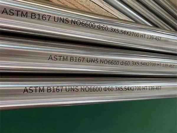
| Nickel-Chromium-Iron Alloy UNS N06600 | 72.0min [Note(2)] | 0.5max | … | 6.0 to 10.0 | 1.0 | 0.15max | 0.5 | 0.15 | 14.0 to 17.0 | … | … | … | … | … | ||
| Nickel-Chromium-Iron Alloy UNS N06690 | 58.0min [Note(2)] | 0.5max | … | 7.0 to 11.0 | 1.0 | 0.15max | 0.5 | 0.1 | 27.0 to 31.0 | … | … | … | … | … | ||
| Nickel-Chromium-Iron Alloy UNS N06025 | Balance [Note(2)] | 0.1max | … | 8.0 to 11.0 | 0.15 | 0.15 to 0.25 | 0.5 | 0.010 | 4.0 to 26.0 | 1.8 to 2.4 | 0.1 to 0.2 | 0.020 max | … | … | ||
| Alloy UNS NO6045 | 45.0min | 0.3max | … | 21.0-25.0 | 1.0 | 0.5-0.15 | 2.5-3.0 | 0.010 | 26.0-29.0 | … | … | 0.020 max | 0.03-0.09 | 0.05-0.12 | 0.1 to 0.10 | 0.05 to 0.12 |
| Nickel-Chromium-Iron Alloy UNS N08800 | 30.0 to 35.0 | 0.75max | … | 39.5min [Note(1)] | 1.5 | 0.10max | 1.0 | 0.015 | 19.0 to 23.0 | 0.15 to 0.60 | 0.15 to 0.60 | … | … | … | ||
| Nickel-Chromium-Iron Alloy UNS N08810 | 30.0 to 35.0 | 0.75max | … | 39.5min [Note(1)] | 1.5 | 0.05to 0.10 | 1.0 | 0.015 | 19.0 to 23.0 | 0.15 to 0.60 | 0.15 to 0.60 | … | … | … | ||
| Nickel-Chromium-Iron Alloy UNS N08811 | 30.0 to 35.0 | 0.75max | … | 39.5min [Note(1)] | 1.5 | 0.06 to 0.10 | 1.0 | 0.015 | 19.0 to 23.0 | 0.15 to 0.60 [Note (2)] | 0.15 to 0.60 [Note (3)] | … | … | … | ||
| Nickel-Chromium-Iron Alloy UNS N08801 | 30.0 to 34.0 | 0.50max | … | 39.5min [Note(1)] | 1.50 | 0.10max | 1.00 | 0.01 | 19.0 to 22.0 | … | 0.75 to 1.5 | … | … | … | ||
| Nickel-Iron-Chromium-Molybdenum-Copper Alloy UNS N08825 | 38.0 to 46.0 | 1.5 to 3.0 | 2.5 to 3.5 | 22.0min [Note(1)] | 1.0 | 0.05max | 0.5 | 0.03 | 19.5 to 23.5 | 0.2max | 0.6 to 1.2 | … | … | … |
NOTE : (1) Maximum unless range is given.
(2) Element shall be determined arithmetically by difference.
(3)Alloy UNS NO8811: Al+Ta, 0.85-1.20
Tensile strength, yield strength, elongation, and Rockwell hardness of the material shall conform to the required mechanical properties set by this specification. Test methods such as chemical analysis, tension, rounding procedure, Rockwell hardness, grain size and hardness conversion shall be performed.
MECHANICAL PROPERTIES OF TUBES
| Material and Condition | Tensile Strength Min. ksi(MPa) | Yield Strength(0.2% Offset)Min,psi(MPa) | Elongation in 2in. or 50mm(or 4D)min. % | Rockwell Hardness(or Equivalent) for Annealed Ends[Note(1)] |
|---|---|---|---|---|
| Nickel UNS N02200: | ||||
| Annealed | 55(379) | 15(103) | 40 | … |
| Stress-relieved | 65(448) | 40(276) | 15 | B65max |
| Low-Carbon Nickel UNS N02201: | ||||
| Annealed | 50(345) | 12(83) | 40 | … |
| Stress-relieved | 60(414) | 30(207) | 15 | B62max |
| Nickel-Copper Alloy UNS N04400: | ||||
| Annelaled | 70(483) | 28(193) | 35 | … |
| Stress-relieved | 85(586) | 55(379) | 15 | B75max |
| Nickel-Chromium-Iron Alloys: | ||||
| Annealad Alloy UNS N06600 | 80(552) | 35(241) | 30 | … |
| Annealad Alloy UNS N06690 | 85(586) | 35(241) | 30 | … |
| Annealad Alloy UNS N06045 | 90(620) | 35(240) | 35 | … |
| Annealad Alloy UNS N06025 | 94(650) | 43(300) | 30 | … |
| Nickel-Iron-Chromium Alloys: | ||||
| Annealed Alloy UNS N08800 | 75(517) | 30(207) | 30 | … |
| Annealed Alloy UNS N08801 | 65(448) | 25(172) | 30 | … |
| Cold-worked Alloy UNS N08810 | 83(572) | 47(324) | 30 | … |
| Annealed Alloy UNS N08810 | 65(448) | 25(172) | 30 | … |
| Annealed Alloy UNS N08801 | 65(448) | 25(172) | 30 | … |
| Nickel-Iron-Chromium-Molybdenum-Copper | ||||
| Annealed UNS N08825 | 58(586) | 35(241) | 30 | … |
ALLOYS, SIZE RANGES, AND YIELD STRENGTH FOR HIGHER YIELD STRENGTH TUBES
| Alloy | Size Range, in. (mm) | 0.2% Yield Strength, ksi (MPa) | ||
|---|---|---|---|---|
| 0D | Wall Thickness | Minimum | Maximum | |
| Nickel-Chromium-Iron Alloy UNS N06600 | 1/4 to 7/8 (6.35 to 22.23) | Up to 0.1000 (2.54) | 40 (276) | 65(449) |
| Nickel-Iron-Chromium Alloy UNS N08800 | 1/4 to 7/8 (6.35 to 22.23) | UP to 0.100 (2.54) | 40 (276) | 65(449) |
| Nickel-Chromium-Iron Alloy UNS N06690 | 1/4 to 7/8 (6.35 to 22.23) | Up to 0.100 (2.54) | 40 (276) | 65(449) |